
Quick Answer
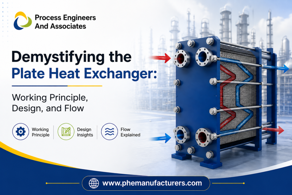
A plate heat exchanger (PHE) transfers heat between two fluids — usually hot and cold — without letting them mix. The fluids flow through alternating narrow channels formed by a stack of corrugated metal plates. Heat passes through the thin plate walls from the hot fluid on one side to the cold fluid on the other, typically in a counter-current flow arrangement for maximum efficiency. This compact design gives PHEs a much higher heat transfer coefficient than traditional shell-and-tube exchangers, making them the preferred choice across dairy, pharma, HVAC, and industrial process cooling applications.
If you’ve ever wondered how an industrial plant heats or cools thousands of litres of fluid an hour using a machine no bigger than a filing cabinet, the answer lies in this deceptively simple stack of steel plates.
What is a Plate Heat Exchanger?
A plate heat exchanger is a type of heat exchanger that uses a series of thin, corrugated metal plates to transfer thermal energy between two fluids. Unlike shell-and-tube exchangers, which rely on bundles of tubes inside a cylindrical shell, a PHE stacks pressed plates together, creating alternating channels for hot and cold fluids.
Each plate is fitted with a gasket (in gasketed models) that seals the channel and directs fluid flow, while corner ports route the hot and cold streams into their respective channels automatically. The result is a compact, high-efficiency unit that does the same job as a much larger shell-and-tube system.
This is precisely the technology behind Gasketed Plate Heat Exchangers, engineered for optimum velocity and turbulence to maximise the overall heat transfer coefficient (U-value) while keeping the required heat transfer area — and capital cost — as low as possible.
The Core Plate Heat Exchanger Working Principle
The plate heat exchanger working principle is built on a simple idea from physics: heat naturally moves from a hotter body to a cooler one until they reach equilibrium. In a PHE, this happens continuously as fluid keeps flowing:
- Hot fluid enters through one set of ports and spreads across alternating channels.
- Cold fluid enters through a separate set of ports and flows through the channels in between.
- Heat passes through the thin plate wall from the hot channel to the adjacent cold channel.
- The corrugated (wavy) pattern on each plate forces the fluid into a turbulent flow rather than a smooth, straight path.
That turbulence is the secret sauce. In a smooth pipe, fluid near the wall barely mixes with fluid in the center, which slows down heat transfer. The corrugations in a plate heat exchanger constantly disturb the flow, keep it churned up, and push more fluid into contact with the plate surface. The result is a much higher heat transfer rate in a much smaller footprint compared to older technologies.
Plate Heat Exchanger Working Principle Explained
The core working principle of a plate heat exchanger rests on three mechanisms working together:
1. Alternating Fluid Channels
Plates are stacked with gaskets that create two separate, sealed flow paths. Hot fluid flows through odd-numbered channels; cold fluid flows through even-numbered channels (or vice versa). The two fluids never physically touch — only the thin plate wall separates them.
2. Counter-Current Flow
In most PHE designs, hot and cold fluids move in opposite directions across adjacent channels. This counter-flow arrangement maintains a consistent temperature difference (ΔT) across the entire plate length, which is far more thermally efficient than parallel flow, where the temperature gap shrinks rapidly.
3. Turbulent Flow Over Corrugated Surfaces
The chevron (herringbone) pattern pressed into each plate forces the fluid into a turbulent, zig-zag path rather than a smooth laminar flow. This turbulence:
- Increases the contact time and surface interaction between fluid and plate
- Reduces the boundary layer resistance to heat transfer
- Minimises fouling and scale build-up on plate surfaces
The combined effect is a heat transfer coefficient that can be 3 to 5 times higher than a comparable shell-and-tube unit, meaning a smaller footprint can achieve the same — or better — thermal performance.
Key Components of a Plate Heat Exchanger
| Component | Function |
| Plates | Corrugated stainless steel (commonly SS304 or SS316L) sheets that form the heat transfer surface |
| Gaskets | Food-grade or industrial elastomer seals that direct fluid flow and prevent leakage/mixing |
| Frame | Fixed and movable end covers that compress the plate pack together |
| Carrying & Guide Bars | Support and align the plates within the frame |
| Tightening Bolts | Compress the plate pack to the correct working pressure |
| Connection Ports | Inlet/outlet points for hot and cold fluid streams |
Plate thickness, corrugation angle, and gasket material are selected based on the fluid type, operating temperature, and pressure — which is why PHE design is rarely “one size fits all.” A dairy pasteurisation line and a hydraulic oil cooling system need very different plate configurations, even though the underlying principle is identical.
Flow Arrangements in Plate Heat Exchangers
Understanding flow arrangement is essential to understanding PHE performance:
- Counter-Current Flow — Fluids flow in opposite directions; delivers the highest thermal efficiency and is the standard configuration for most industrial applications.
- Co-Current (Parallel) Flow — Fluids flow in the same direction; used in specific cases where temperature control needs to be gentler or more uniform.
- Single-Pass vs. Multi-Pass — In a single-pass unit, fluid crosses the plate pack once. Multi-pass configurations route fluid back and forth for applications needing a larger temperature change or unequal flow rates between the two fluids.
The number of plates, their corrugation pattern, and the port arrangement together determine the pressure drop, flow velocity, and final outlet temperature — all of which are calculated during the design and application engineering stage before manufacturing begins.
Why Plate Heat Exchangers are More Efficient than Shell-and-Tube Units
| Factor | Plate Heat Exchanger | Shell-and-Tube Exchanger |
| Heat transfer coefficient | High (turbulent flow) | Lower (often laminar) |
| Footprint | Compact | Bulky |
| Maintenance access | Easy — plates can be opened and cleaned | Difficult — requires tube bundle removal |
| Capacity expansion | Add plates as needed | Requires new unit |
| Scaling/fouling | Lower, due to turbulence | Higher, due to laminar flow zones |
| Capital cost | Lower for equivalent duty | Higher |
This efficiency advantage is why industries ranging from dairy and beverage processing to steel, pharma, and HVAC have steadily shifted toward plate technology for pasteurisation, oil cooling, chilled water transfer, and waste-heat recovery applications.
Real-World Applications Where this Principle Matters
- Dairy industry — Milk pasteurisation relies on precise, rapid heating and cooling cycles that PHEs deliver through tight temperature control across the plate pack.
- HVAC systems — Chilled water is transferred from chiller units to process water loops without cross-contamination.
- Steel and induction furnace cooling — High turbulence prevents scale build-up even with less-than-ideal water quality, a common industrial challenge.
- Pharmaceutical processing — Hygienic, easy-to-open plate packs support strict cleaning validation requirements.
Each of these use cases depends on the same fundamental principle — controlled, turbulent, counter-current heat exchange across thin metal plates — engineered differently for the specific fluid, temperature range, and pressure involved.
Expert Tip: Getting the Design Right Matters More Than the Concept
Understanding the working principle is only half the picture. In practice, performance depends on correct thermal and hydraulic design calculations — plate count, corrugation angle, gasket material selection, and flow velocity — matched precisely to your process conditions. An undersized or poorly specified PHE will scale faster, lose efficiency, and increase long-term operating costs, even though the basic principle is sound.
This is where application engineering and requirement analysis, done before manufacturing, make the real difference between a PHE that performs for years and one that underdelivers from day one.
For a deeper technical reference on heat exchanger classifications and design standards, the Engineering Toolbox’s overview of heat exchanger types is a useful external resource.
FAQs
1. What is the basic working principle of a plate heat exchanger?
A plate heat exchanger transfers heat between two fluids flowing through alternating channels formed by stacked corrugated plates, typically in a counter-current arrangement, without the fluids mixing.
2. Why is counter-current flow preferred in plate heat exchangers?
Counter-current flow maintains a more consistent temperature difference along the plate length, allowing higher overall heat transfer efficiency than parallel (co-current) flow.
3. What materials are plate heat exchanger plates made of?
Plates are commonly made from stainless steel grades like SS304 or SS316L, chosen for corrosion resistance, hygiene, and durability under varying temperature and pressure conditions.
4. How is a plate heat exchanger different from a shell-and-tube exchanger?
A PHE uses stacked plates to create turbulent flow and a higher heat transfer coefficient in a compact footprint, while a shell-and-tube exchanger uses tube bundles inside a shell, generally requiring more space for the same thermal duty.
5. Can plate heat exchangers be customised for specific industries?
Yes. Plate count, gasket material, corrugation pattern, and port configuration can all be engineered around the specific fluid, temperature, pressure, and hygiene requirements of an industry such as dairy, pharma, or steel processing.
Conclusion
The plate heat exchanger’s working principle is elegantly simple — alternating channels, turbulent flow, and counter-current heat transfer across corrugated plates — but achieving reliable, long-term performance depends entirely on correct design and engineering behind that principle. Whether you’re pasteurising milk, cooling induction furnaces, or managing chilled water in an HVAC loop, the right plate configuration makes the difference between an efficient system and a costly one.
Need a Plate Heat Exchanger engineered around your exact process conditions? Get in touch with PHE India for application engineering, custom design, and manufacturing support — or explore our Industrial PHE and Food Grade PHE ranges to find the right fit for your industry.
Website: https://phemanufacturers.com/
Call: 93505 45996, 85274 55996
Mailto: sales@phe-india.in